1.7 KiB
1.7 KiB
Source can be found here: git.jojeee.xyz
===> always generate new gerbers to be 100% up to date <===
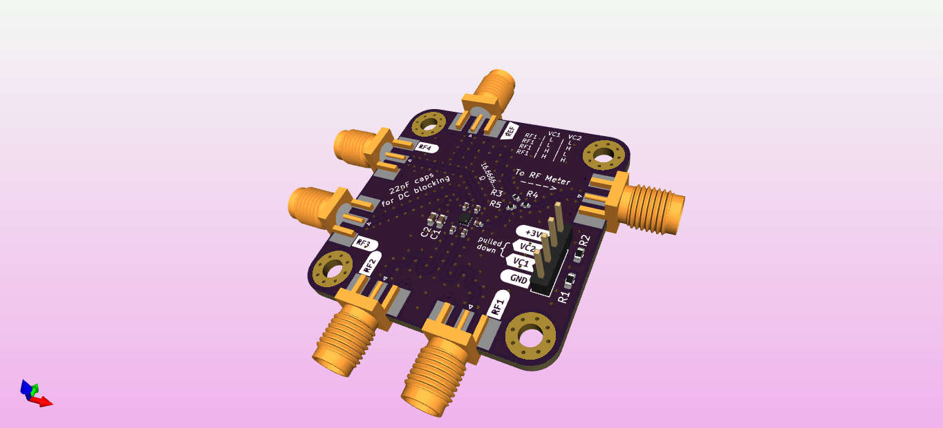
What even is this?
- It is a small board that will help measure the phase offset between a reference signal and 1/4 inputs.
- A quick and dirty way of knowing if the two measured signals are in/out of phase was needed. The resistor combiner allows a device to measure either a null or max output power depending on the inputs' destructive/constructive interference.
What does this mean?
- Absolute phase offsets are not easily obtainable using this method
- The phase of each input can be tuned until the output reaches a minimum/maximum output, this indicates 180/0 phase difference respectively
- Due to issues with dynamic range, the null points (180 degree destructive intfer.) are easier to measure
Why was it made?
- This board is to prove out a relatively novel way of phase matching a large number of HackRF SDRs, for use in phased antenna arrays
- The board will hopefully prove the technique's ability to work with 4 units and from there it can be scaled up ~40/50 element arrays (each element powered by a separate radio)
Critiques
- The aim was to get a switch that would allow signals with frequencies up to 6GHz to be used. In practice with the type of substrate used, the design is not likely to perform well
- The board was manufactured via JLCPCB and even it is made using a controlled FR4-like material, it likely is not performant enough at the higher frequencies. Consequently, if not being used at those higher frequencies, the switch chosen could have been cheaper and have been in a more accessible package.