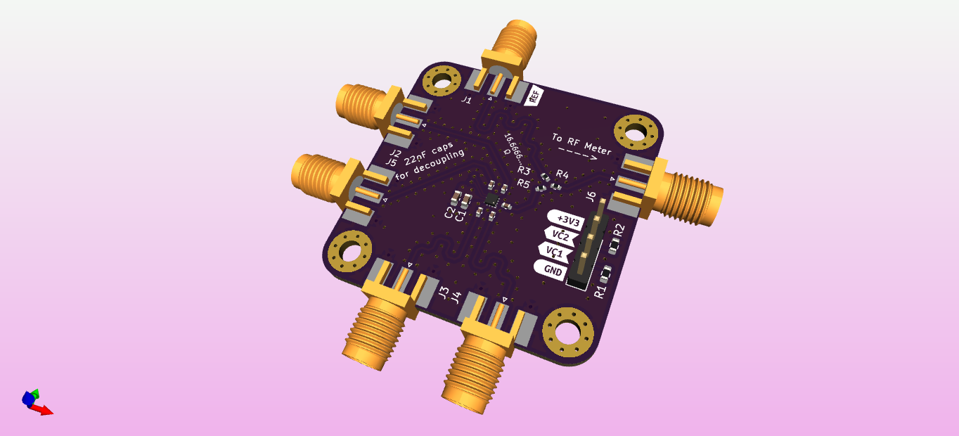
It is a small board that will help measure the phase offset between a reference signal and 1/4 inputs.
A quick and dirty way of knowing if the two measured signals are in/out of phase was needed. The resistor combiner allows a device to measure either a null or max output power depending on the inputs' destructive/constructive interference.
What does this mean?
Absolute phase offsets are not easily obtainable using this method
The phase of each input can be tuned until the output reaches a minimum/maximum output, this indicates 180/0 phase difference respectively
Due to issues with dynamic range, the null points (180 degree destructive intfer.) are easier to measure
Why did I make it?
This board is to prove out a relatively novel way of phase matching a large number of HackRF SDRs, for use in phased antenna arrays
The board will hopefully prove the technique's ability to work with 4 units and from there it can be scaled up ~40/50 element arrays (each element powered by a separate radio)